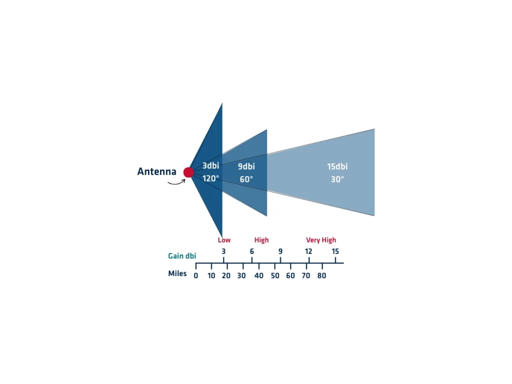
Antenna gain refers to the ability of the antenna to focus signal energy in specific directions. It directly affects signal reception quality. Higher gain improves sensitivity and signal-to-noise ratio, especially in challenging environments.
First, GNSS antennas typically have low to moderate gain. This allows them to receive signals from multiple satellites across the sky. Unlike directional antennas, GNSS antennas use an omnidirectional or hemispherical pattern. Next, the signal energy is measured in decibels relative to an isotropic radiator (dBi). A higher dBi value means the antenna focuses energy more effectively. GNSS antennas usually range between 0 dBi and 5 dBi. Then, gain affects the antenna’s reception pattern. A well-designed antenna ensures consistent gain across the upper hemisphere. This enables reliable tracking of satellites at different elevations.
Additionally, gain performance depends on antenna type and application. Geodetic-grade antennas offer stable gain and low noise. They provide consistent performance over long observation sessions. Moreover, gain uniformity helps reduce multipath effects. Antennas with low gain near the horizon reject reflected signals from buildings and terrain. This enhances measurement accuracy.
It is very important to balance gain and pattern shape. Increasing gain too much can narrow the reception beam. This could reduce satellite visibility near the horizon. Also, gain depends on the internal structure of the antenna. Patch, quadrifilar helix, and choke-ring antennas offer different gain characteristics. Choke-ring type, for example, combine stable gain and multipath rejection. Manufacturers provide gain specifications and radiation patterns. These help users select suitable antennas for their applications. Accurate gain data is essential for modeling antenna performance in GNSS processing.
These plays a key role in signal quality and positioning accuracy. Understanding gain behavior helps optimize receiver performance in various operational environments. Proper antenna selection ensures reliable GNSS data across all conditions.
Explore our comprehensive range of GNSS antennas.
Do you have questions?
What are the GNSS frequencies and signals ?
▶︎ GPS
Signals and Frequencies
L1 C/A → 1575.42 MHz
L1C → 1575.42 MHz
L2 C → 1227.6 MHz
L2 P → 1227.6 MHz
L5 → 1176.45 MHz
▶︎ GLONASS
Signals and Frequencies
L1 C/A → 1598.0625-1609.3125 MHz
L2 C → 1242.9375-1251.6875 MHz
L2 P → 1242.9375-1251.6875 MHz
L3 → OC 1202.025
▶︎ GALILEO
Signals and Frequencies
E1 → 1575.42 MHz
E5a → 1176.45 MHz
E5b → 1207.14 MHz
E5 AltBOC → 1191.795 MHz
E6 → 1278.75 MHz
▶︎ BeiDou
Signals and Frequencies
B1I → 1561.098 MHz
B2I → 1207.14 MHz
B3I → 1268.52 MHz
B1C → 1575.42 MHz
B2a → 1176.45 MHz
B2b → 1207.14 MHz
▶︎ NAVIC
Signals and Frequencies
L5 → 1176.45 MHz
▶︎ SBAS
Signals and Frequencies
L1 → 1575.42 MHz
L5 → 1176.45 MHz
▶︎ QZSS
Signals and Frequencies
L1 C/A → 1575.42 MHz
L1 C → 1575.42 MHz
L1S → 1575.42 MHz
L2C → 1227.6 MHz
L5 → 1176.45 MHz
L6 → 1278.75 MHz
What is GNSS post-processing?
GNSS post-processing, or PPK, is an approach where the raw GNSS data measurements logged on a GNSS receiver are processed after the data acquisition activity. They can be combined with other sources of GNSS measurements to provide the most complete and accurate kinematic trajectory for that GNSS receiver, even in the most challenging environments.
These other sources can be local GNSS base station at or near the data acquisition project, or existing continuously operating reference stations (CORS) typically offered by governmental agencies and/or commercial CORS network providers.
A Post-Processing Kinematic (PPK) software can make use of freely available GNSS satellite orbit and clock information, to help further improve the accuracy. PPK allow for precise determination of a local GNSS base station’s location in an absolute global coordinate reference frame datum, which is used.
PPK software can also support complex transformations between different coordinate reference frames in support of engineering projects.
In other words, it gives access to corrections, enhances the project’s accuracy, and can even repair data losses or errors during the survey or installation after the mission.
Which GNSS antenna works best for RTK, PPP, and PPK?
The best type of GNSS antenna for RTK (Real-Time Kinematic), PPP (Precise Point Positioning), and PPK (Post-Processed Kinematic) depends on your accuracy requirements, environment, and application. However, certain antenna characteristics and types consistently perform better in high-precision GNSS workflows.
| Application | Best Antenna Type | Notes |
|---|---|---|
| RTK (rover/base) | Survey-grade or choke ring | Choke ring for base; survey-grade for rover |
| PPK (UAVs, mobile mapping)
PPP (static or dynamic) |
Survey-grade or helical
Survey-grade or choke ring |
Compact with good PCV handling
Stable phase center is key |
If you’re working with SBG Systems GNSS/INS solutions, use antennas that are officially recommended or tested for compatibility with your system’s GNSS receiver capabilities (e.g., multi-band/multi-constellation) to ensure optimal results in RTK, PPP, and PPK workflows.